Replacing Leaky Capacitors
 If you have a circuit board with leaky or busted capacitors, it’s relatively easy to replace them yourself. Here’s my tools of the trade and quick tips:
Not for the squeamish
- Don’t try any of this if you don’t have the tools, time or patience to try. Hire someone like Uniserver (aka MacCaps) or a suitable electronics tech instead.
Tools
- Have a good soldering iron, hot enough to melt the solder on the board. I’ve been using a cheapo Weller WPS18MP.
- Use good solder.
- Unfortunately, I don’t personally know what this is. Super thin solder is best because it allows you to work with only what you need. I have an ancient roll of super thick 60/40 rosin core solder from Radio Shack from the ’80s. It’s messier than I like, but it’s cheaper than buying new.
- Solder removal tools
- Get whatever you like that’s in your budget.
- “Helping Hands”
- A device that allows you to mount the subject materials, leaving your hands free for solder and iron.
- Flush shear pliers.
- I don’t know what these are called in reality. I purchased Xcelite Shearcutters 170M, flush cut.
- Jumper Wire
- 30AWG Wire Wrap works well in most cases, but it depends on your load voltage.
- Safety Glasses
- You’re going to be cutting through things. Metal things. You don’t want metal things in your eyes. Bad mojo.
- Capacitor replacement guide
- Use your best friend (read: Google) to find a capacitor replacement guide for your particular machine. Read it several times. Read it again. Buy the capacitors the guide says your machine needs. (Digi-Key and Mouser Electronics are good sources)
- If you can’t find a capacitor replacement guide, then research, research research. Find out how to read the markings on your capacitors so you know which ones to purchase.
Tips
- Soldering Guides
- Find one on YouTube and watch it several times. Then find another, do the same. Do this over and over again until you understand the concept of soldering.
- Removing Old Capacitors
- Read this.
- Then read this.
- Read this too.
- Be aware of the circuits on which you’re working. Logic-only boards are pretty safe but high-voltage analog boards or power supplies with high value capacitors and transformers can ruin your day with a nasty shock. Read up on these and how to discharge them safely.
- If after reading all of that you’re squeamish about the process, contact this guy or find yourself a suitable electronics tech and have him or her do it for you.
- On the below struck-through items: these processes are no longer recommended. They work, but have higher than average likelihood of destroying traces.
Axial Lead or Radial Lead CapacitorsIf the capacitor is flush to the boardCut through the capacitor about 1mm above the board. Then carefully cut through the remaining bits of the capacitor perpendicular to the board surface being very careful not to scratch any board traces. Then use the shears to carefully grab one of the leads. Heat the solder until it liquefies and pull up on the lead. It should come out of the hole easily.
If the capacitor has visible leadsCut off the leads close to but not flush with the board surface. Then use the shears to carefully grab one of the leads. Heat the solder until it liquefies and pull up on the lead. It should come out of the hole easily.
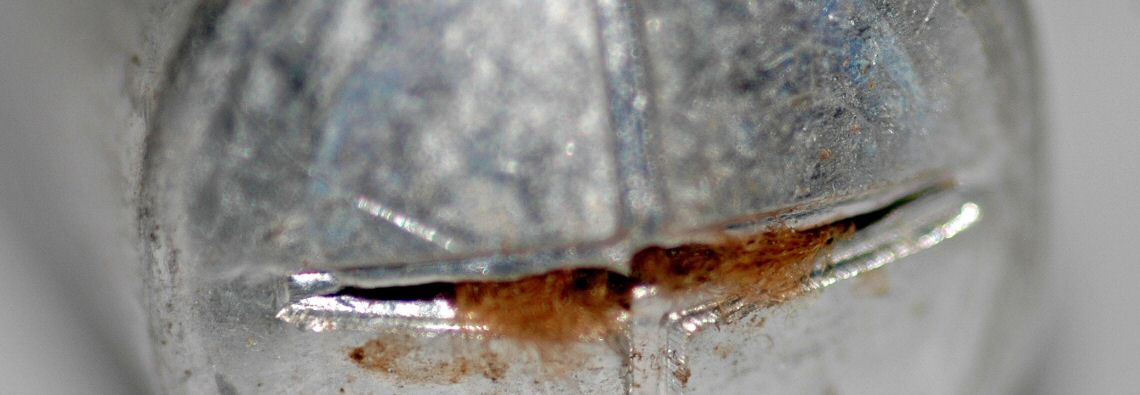
Surface Mount SolidNOTE: Never ever pull up on, rock side to side, push around or press down on a surface mount capacitor. The pads they connect to are very fragile and can pull off the board. If they come off completely, you’re going to have a bad day.Heat the solder on one side and use a solder removal tool remove the solder. Repeat on the other side. Keep repeating until you see the capacitor move off the pads on it’s own.
Surface Mount “Can”NOTE: Never ever pull up on, rock side to side, push around or press down on a surface mount capacitor. The pads they connect to are very fragile and can pull off the board. If they come off completely, you’re going to have a bad day.Cut through the capacitor about 1mm above the plastic base parallel to the direction of the pads. Remove the bulk of the capacitor (if it hasn’t already flown across your room somewhere. They tend to do this).Cut off the tops of the leads you see poking out through the base. These usually will look mushroom shaped – you’re going for removing the little heads on them and making them nice and cleanly cut.Remove any of the stuff that might be left in the base until you’re left with only the plastic base. Cut across the stuff with your shears and then use tweezers for this bit. If there’s any resistance, you’re using too much force. Cut more. Be patient and take your time.Once you are reduced to the plastic base, you should be able to very carefully lift the pad off the remaining leads with tweezers.
- Adding new capacitors
- Through Hole
- Stick the leads through the holes minding the polarity, then add just enough solder to fill up the hole. Piece of cake.
- Surface Mount
- Tin both sides of the capacitor first. Helping hands really help here – you can put the capacitor in one of the clips and use your free hands for solder and iron. Also keeps sensitive fingers away from hot metal.
- Use tweezers to hold the capacitor over the pads. Get it centered, mind the polarity and melt the solder on one side. Wait for it to solidify then melt the other side. Done.
- Through Hole
- Lifted Pads
- First: Don’t Panic. It happens even to professionals.
- If you’ve lifted the pad but not completely ripped it from the surface (i.e. it’s still sticking up a little bit)
-
- Carefully put a very small amount of superglue on the board with the tip of a toothpick, and press the pad down with a clean pick. Wait 5 minutes, then complete the job.
- If you’ve lifted the pad but completely ripped it from the surface
- Trace the pad back on the board and find either a remaining trace or a via “hole” your trace leads to. (You may find it also leads to another component – this can work too.)
- If you still have a trace left, you can use a sharp tool to carefully scrape the insulating layer, exposing the trace. From there, you might be able to throw on a big solder blob and get it to work, or solder a jumper wire to the trace, then to the capacitor.
- If you have nothing left at all, then you’ve probably pulled it out all the way to a via. Solder the good end of the capacitor to the board first. Then solder a jumper wire to then open end of the capacitor, then to the via, running it through the hole if possible. If the via does not have a suitable diameter to run the wire through it, I find it helps to use a spudger or toothpick to press the jumper wire flush to the board before hitting it with the iron. Don’t know why this works, but it seems to. Notes on using jumper wire.