Using 4164 Chips to emulate MK 4332 Chips
Project
Adapt a replacement for MK 4332 RAM chips (32k x 1bit)
Theory
The 4332 chip is really just two 4116 chips sandwiched together, with a separate pair of CAS/RAS lines for the second chip modules.
You can emulate this easily by stacking two 4164 chips together, soldering all the address and power rails together, but keeping their CAS/RAS lines separate, and routing the second pair of CAS/RAS lines to the second chip with fly leads.
NOTE: you can also do this with 4116 chips by adapting the procedure. See end notes.Materials/Tools
- 2x 4164 chips
- 1x spare old component lead or scrap piece of wire.
- 1x 2cm lengths of solid core wire, 22/24 gauge.
- Flush Cutters
- Wire Strippers
- Solder and soldering iron
Process
Prepare Chips for proper voltage operation
- Remove pin 1 from both 4164 chips. (because we don’t need -5 volts!)
Prepare bottom chip
- Ensure all pins are aligned as if the chip is ready to insert into a socket. (i.e. remove the slight factory bend)
- Bend pin 8 nearly straight upward, very slowly and carefully
Prepare Top chip
- Bend pin 8 up, and curl it over top of the chip toward pin 9.
- Use a small piece of 24 gauge wire or a spare component lead to solder pin 8 to pin 9.
- Bend pin 4 and pin 15 straight out.
- Remove the thinner portion and about half of the thicker portion of pins 4 and 15, but leave a small stub to solder to.
- Bend the remaining pins outward slightly more than the factory angle by a couple degrees. You’re aiming to have the chips stack together nicely.
Assemble Stack
Lay the chips together so that the pins align number to number. Solder the following pins together.
top chip    [   2  3     5  6  7 8]
bottom chip [   2  3     5  6  7 8]

top chip    [9 10 11 12 13 14    16]
bottom chip [9 10 11 12 13 14    16]
Add RAS2 and CAS2 Wires
- Cut two 2cm lengths of solid core wire. 24-22 gauge is best for this. Thicker won’t fit in sockets, and thinner may fall out of sockets.
- Remove the proper amount of jacket from each one. About 1mm on one side, and 3mm on the other
- Solder the 1cm ends to the stubs of pins 4 and 15 of the TOP chip.
Insert into socket
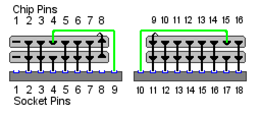
- Insert the chips into the sockets so that pin 1 would go in hole one… if pin 1 existed. 😉
- The fly lead from pin 4 goes into pin 9 on the socket.
- The fly lead from pin 15 goes into pin 10 on the socket.
- For reference: these are the two open holes in the socket on the end farthest away from pin 1.
And that’s it!
When you’re done, it should look like this
Adapting the procedure for 4116 Chips
- Don’t remove pin 1 from either chip.
- Don’t remove or bend over pin 8 on either chip.
- Ensure you solder pins 1 to 1 and pins 8 to 8 on both chips.